When the sweltering summer heat hits, we rely heavily on our central air conditioning systems to keep us comfortable. But have you ever wondered what goes on behind the scenes? Understanding the various components of your AC unit, and particularly their layout, can help you grasp its function and even troubleshoot minor issues. This is where a central air parts diagram comes into play.
The Big Picture: A System of Interconnected Parts
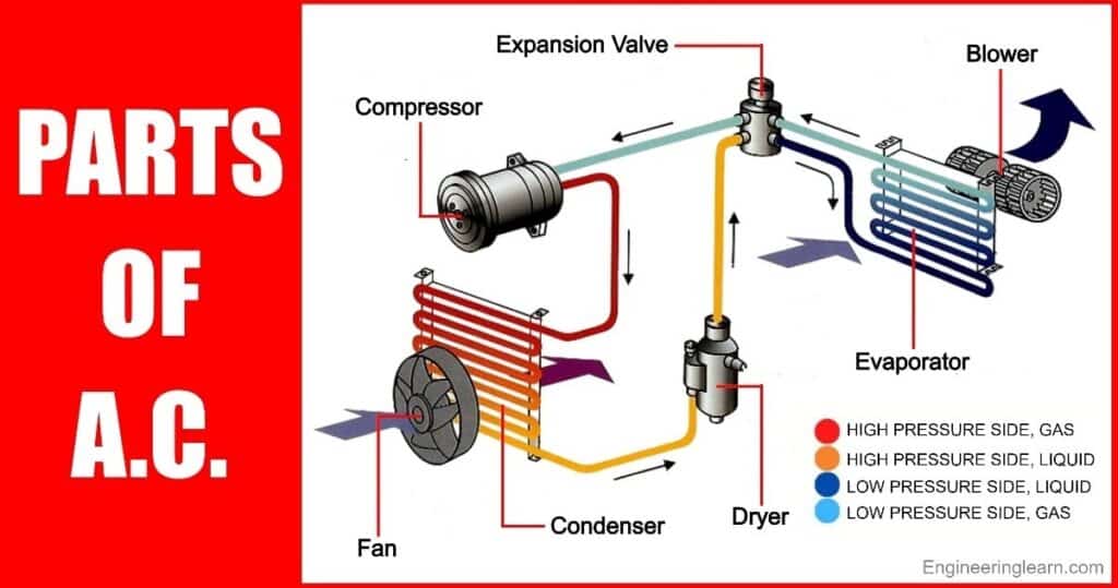
A central air conditioning system is not a single unit but a network of components working in harmony. Broadly, it can be divided into two main sections: the outdoor unit (condenser) and the indoor unit (evaporator), connected by refrigerant lines. Within each unit, various parts perform specific tasks. A diagram helps illustrate how these parts interact.
Key Components and Their Roles
Let’s delve into the critical components you’d find on a central air parts diagram:
- Outdoor Unit (Condenser):
- Compressor: Often considered the heart of the system, the compressor pressurizes the refrigerant, raising its temperature. It’s a vital (and often expensive) part.
- Condenser Coil: This coil is where the hot refrigerant releases its heat to the outside air. It’s typically a series of metal tubes with fins to maximize surface area.
- Condenser Fan: This fan pulls air across the condenser coil, facilitating heat transfer.
- Refrigerant Lines: These copper pipes carry refrigerant between the indoor and outdoor units.
- Indoor Unit (Evaporator):
- Evaporator Coil: Here, the refrigerant absorbs heat from the indoor air, cooling it down. This coil is typically located within the air handler or furnace.
- Blower Fan: This powerful fan circulates the cooled air through your ductwork and into your home.
- Expansion Valve (or Metering Device): This valve controls the flow of refrigerant into the evaporator coil, helping it to change from a liquid to a gas as it absorbs heat.
- Air Filter: Usually found near the air intake, the filter removes dust, pollen, and other contaminants from the air before it enters the system.
- Drain Pan and Line: This pan collects condensation formed on the evaporator coil, and a drain line carries this water away.
Why Understanding a Parts Diagram Matters
A central air parts diagram isn’t just for HVAC technicians. Here’s why it’s beneficial for homeowners:
- Basic Troubleshooting: Understanding the system’s layout can help you identify potential problems, like a frozen coil or a clogged drain line.
- Communication with Professionals: When you need to call a technician, being familiar with the parts and their functions enables you to describe the issue more effectively.
- Preventive Maintenance: Knowing where the air filter is, for instance, makes it easier to remember to change it regularly, which is key for optimal system performance and air quality.
- Appreciation of Function: Gaining an understanding of how the various parts work together will deepen your appreciation for the complexity and ingenuity of your home’s cooling system.
Conclusion
While an intricate system, understanding the basic parts of your central air conditioner is not as complex as it may initially appear. A central air parts diagram serves as a roadmap, helping you to recognize the individual components and how they contribute to creating a cool and comfortable living space. This knowledge empowers you to be a more informed homeowner and ensures you get the most out of your HVAC system.